
GPU Gems 3
GPU Gems 3 is now available for free online!
The CD content, including demos and content, is available on the web and for download.
You can also subscribe to our Developer News Feed to get notifications of new material on the site.
Chapter 23. High-Speed, Off-Screen Particles
Iain Cantlay
NVIDIA Corporation
Particle effects are ubiquitous in games. Large particle systems are common for smoke, fire, explosions, dust, and fog. However, if these effects fill the screen, overdraw can be almost unbounded and frame rate problems are common, even in technically accomplished triple-A titles.
Our solution renders expensive particles to an off-screen render target whose size is a fraction of the frame-buffer size. This can produce huge savings in overdraw, at the expense of some image processing overhead.
23.1 Motivation
Particle systems often consume large amounts of overdraw and fill rate, leading to performance issues. There are several common scenarios and associated hazards.
Particle systems may model systems with complex animated behavior—for example, a mushroom cloud or an explosion. Such effects can require many polygons, maybe hundreds or thousands.
Particles are often used to model volumetric phenomena, such as clouds of fog or dust. A single, translucent polygon is not a good model for a volumetric effect. Several layers of particles are often used to provide visual depth complexity.
Many game engines have highly configurable particle systems. It can be trivial to add lots of particles, leading to a conflict with performance constraints.
Worse, the camera view is often centered on the most interesting, intense effects. For first-person and third-person games, weapon and explosion effects are usually directed at the player character. Such effects tend to fill the screen and even a single-particle polygon can easily consume an entire screen's worth of overdraw.
Fortunately, many of the effects modeled with particles are nebulous and soft. Put more technically, images of smoke and fog have only low frequencies, without sharp edges. They can be represented with a small number of samples, without loss of visual quality. So a low-resolution frame buffer can suffice.
Conversely, our technique is less well suited to particles with high image frequencies, such as flying rock debris.
23.2 Off-Screen Rendering
Particles are rendered to an off-screen render target whose size is a fraction of the main frame buffer's size. We do not require a particular ratio of sizes. It can be chosen by the application, depending on the speed-quality trade-off required. Our sample application provides scales of one, two, four, and eight times. Scales are not restricted to powers of two.
23.2.1 Off-Screen Depth Testing
To correctly occlude the particles against other items in the scene requires depth testing and a depth buffer whose size matches our off-screen render target. We acquire this by downsampling the main z-buffer. The basic algorithm is this:
- Render all solid objects in the scene as normal, with depth-writes.
- Downsample the resulting depth buffer.
- Render the particles to the off-screen render target, testing against the small depth buffer.
- Composite the particle render target back onto the main frame buffer, upsampling.
Figure 23-1 shows the first, third, and fourth stages. (It is not easy to show a meaningful representation of the depth buffer.) The orange arrow shows how the depth test creates a silhouette of the solid objects in the off-screen render target.
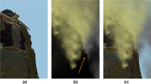
Figure 23-1 The Steps of the Basic Off-Screen Algorithm
23.2.2 Acquiring Depth
Conceptually, the preceding algorithm is straightforward. The devil is in the details.
Acquiring Depth in DirectX 9
Under DirectX 9, it is not possible to directly access the main z-buffer. Depth must be explicitly created using one of three methods.
Multiple render targets (MRTs) can be used: Color information is written to the first target; depth is written to the second. There are a couple of disadvantages to this approach. All targets must have equal bit depths. The back buffer will be 32-bit (or more), but less might suffice for depth. More seriously, MRTs are not compatible with multisample antialiasing (MSAA) in DirectX 9.
Alternatively, depth can be created by writing to a single render target in a separate pass. This has the obvious disadvantage of requiring an extra pass over most of the scene's geometry, or at least that part which intersects the particle effect. On the plus side, depth can be written directly at the required off-screen resolution, without a downsampling operation.
Depth can also be written to the alpha channel of an RGBA target, if alpha is not already in use. A8R8G8B8 might not have sufficient precision. It is quite limited, but it might work, if the application has a small range of depths. A16B16G16R16F is almost ideal. It has the same memory footprint of the MRT option. But again, MSAA is not supported on GeForce 6 and GeForce 7 Series cards.
None of these options is ideal. Depending on the target application, the issues may be too constraining. The lack of MSAA is a major stumbling block for games in which MSAA is an expected feature.
This is all rather frustrating, given that the graphics card has the required depth information in its depth buffer. On a console platform, you can simply help yourself to depth data. Perennially, at presentations on DirectX, someone asks, "When will we be able to access the z-buffer?"
DirectX 10 finally provides this feature—sort of.
Acquiring Depth in DirectX 10
DirectX 10 allows direct access to the values in the depth buffer. Specifically, you can bind a shader resource view (SRV) for the depth surface. Unsurprisingly, you must unbind it as a render target first. Otherwise, it is fairly straightforward.
There is still a catch. It is not possible to bind an SRV for a multisampled depth buffer. The reason is fairly deep. How should an MSAA resolve operation be applied to depth values? Unlike resolving color values, an average is incorrect; point sampling is also wrong. There is actually no correct answer. For our application to particles, point sampling might be acceptable. As will be discussed later, we prefer a highly application-specific function. And that's the point: it needs to be application specific, which is not supported in DirectX 10. However, support is planned for DirectX 10.1 (Boyd 2007).
Fortunately, most of the restrictions that applied to the DirectX 9 options have been lifted in DirectX 10. MRTs work with MSAA, and MRT targets can have different bit depths. There are also no restrictions on the use of MSAA with floating-point surface formats.
Our sample code demonstrates two options in DirectX 10: In the absence of MSAA, it binds the depth buffer as an SRV; when MSAA is used, it switches to the MRT method.
23.3 Downsampling Depth
Regardless of how we acquire depth values, the depth surface needs to be downsampled to the smaller size of the off-screen render target. (Actually, this is not true of rendering depth only in a separate pass. However, this method is equivalent to point-sampling minification.) As discussed previously for the MSAA resolve, there is no universally correct way to downsample depth.
23.3.1 Point Sampling Depth
Simply point sampling depth can produce obvious artifacts. In Figure 23-2, the green triangle is a foreground object, close to the view point, with a low depth value. The white background areas have maximum depth. The 16 pixels represented by the dotted lines are downsampled to 1 off-screen pixel. Point A is where we take the depth sample. It is not representative of most of the 16 input pixels; only pixel B has a similar depth.
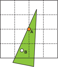
Figure 23-2 Point Sampling from 16 Pixels to 1
If the green triangle is a foreground object with a particle behind, the depth test will occlude the particle for the low-resolution pixel and for all 16 high-resolution pixels. The result can be a halo around foreground objects. The center image of Figure 23-3 shows such a halo. (The parameters of Figure 23-3 are chosen to highly exaggerate the errors. The scaling is extreme: 8x8 frame-buffer pixels are downsampled to 1x1 off-screen pixels. The colors are chosen for maximum contrast: yellow background and red particles. And linear magnification filtering is disabled to show individual low-resolution pixels.)
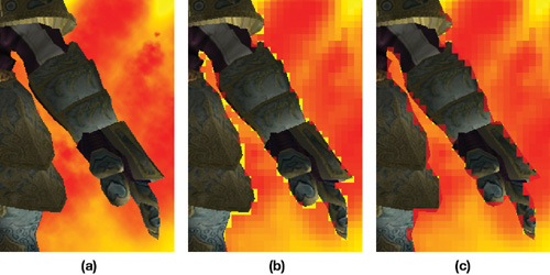
Figure 23-3 The Effects of Downsampled Depth Exaggerated
In some cases, the halos may be acceptable. For example, on a very fast moving effect such as an explosion, you may not notice the detail. Figure 23-4 shows a more realistic example, with more natural colors, a 2x2 to 1x1 downsample, and linear filtering.
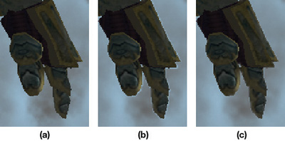
Figure 23-4 The Effects of Downsampled Depth on a Natural Scene
23.3.2 Maximum of Depth Samples
The halos can be improved by doing more than a single point sample. The right-hand images in Figures 23-3 and 23-4 show the result of applying a maximum function when downsampling. We sample a spread of four depth values from the full-resolution depth data and take the maximum one. This has the effect of shrinking the object silhouettes in the off-screen image of the particles. The particles encroach into the solid objects. There is absolutely no physical or theoretical basis for this. It just looks better than halos. It's an expedient hack. This is why depth downsampling functions have to be application defined.
Only four samples are taken. This completely eliminates the halos in Figure 23-4 because the four samples fully represent the high-resolution data. In Figure 23-3 however, four depth samples do not completely represent the 8x8 high-resolution pixels that are downsampled. So there are still minor halo artifacts. These are small enough that they are largely hidden by linear blending when the low-resolution particle image is added back to the main frame buffer.
23.4 Depth Testing and Soft Particles
Depth testing is implemented with a comparison in the pixel shader. The downsampled depth buffer is bound as a texture (an SRV in DirectX 10). The depth of the particle being rendered is computed in the vertex shader and passed down to the pixel shader. Listing 23-1 shows how the pixel is discarded when occluded.
Example 23-1. The Depth Test Implemented in the Pixel Shader
float4 particlePS(VS_OUT vIn) : COLOR
{
  float myDepth = vIn.depth;
  float sceneDepth = tex2D(depthSampler, vIn.screenUV).x;
  if (myDepth > sceneDepth)
    discard;
  // Compute color, etc.
  ...
}
Given that we have access to the particle and scene depth in the pixel shader, it is trivial to additionally implement soft particles. The soft particles effect fades the particle alpha where it approaches an intersection with solid scene objects. Harsh, sharp intersections are thus avoided. The visual benefits are significant. Listing 23-2 shows the required pixel shader code. Note that the zFade value replaces the comparison and discard; zFade is zero where the particle is entirely occluded.
Example 23-2. Soft Particles Are Better Than a Binary Depth Test
float4 particlePS(VS_OUT vIn) : COLOR
{
  float myDepth = vIn.depth;
  float sceneDepth = tex2D(depthSampler, vIn.screenUV).x;
  float zFade = saturate(scale * (myDepth - sceneDepth));
  // Compute (r,g,b,a), etc.
  ... return float4(r, g, b, a * zFade);
}
We will not discuss soft particles further here. They are only a nice side effect, not the main focus. The technique is thoroughly explored in NVIDIA's DirectX 10 SDK (Lorach 2007).
23.5 Alpha Blending
Partly transparent particle effects are typically blended into the frame buffer. Alpha-blending render states are set to create the blending equation:
|
p 1 = d(1 - 1) + s 11, |
where p 1 is the final color, d is the destination color already in the frame buffer, and s 1 and 1 are the incoming source color and alpha that have been output by the pixel shader. If more particles are subsequently blended over p 1, the result becomes
|
p 2 = (p 1)(1 - 2) + s 22 = (d(1 - 1) + s 11)(1 - 2) + s 22, |
|
p 3 = (p 2)(1 - 3) + s 33 = ((d(1 - 1) + s 11)(1 - 2) + s 22(1 - 3) + s 33, |
and so on for further blended terms. Rearranging the equation for p 3 to group d and s terms gives
|
p 3 = d(1 - 1)(1 - 2)(1 - 3) + s 11(1 - 2)(1 - 3) + s 22(1 - 3) + s 33. |
We have to store everything except the frame-buffer d term in our off-screen render target. The final compose operation then needs to produce p 3, or more generally p n .
Take the d term first—that is simpler. It is multiplied by the inverse of every alpha value blended. So we multiplicatively accumulate these in the alpha channel of the render target.
Next, examine the s terms contributing to p 3. Note that they take the same form as the conventional alpha-blending equations for p 2, p 3, etc., if the target is initialized to zero:
|
0(1 - 1) + s 11 |
|
0(1 - 1)(1 - 2) + s 11 (1 - 2) + s 22 |
|
0(1 - 1)(1 - 2)(1 - 3) + s 11 (1 - 2)(1 - 3) + s 22 (1 - 3)+ s 33 |
So we accumulate the s terms in the RGB channels with conventional alpha blending. The blending equations are different for the color channels and the alpha channel. The SeparateAlphaBlendEnable flag is required. Listing 23-3 shows the DirectX 9 blending states required. Additionally, we must clear the render target to black before rendering any particles.
Example 23-3. Alpha-Blending States for Rendering Off-Screen Particles
AlphaBlendEnable = true;
SrcBlend = SrcAlpha;
DestBlend = InvSrcAlpha;
SeparateAlphaBlendEnable = true;
SrcBlendAlpha = Zero;
DestBlendAlpha = InvSrcAlpha;
It is also common to additively blend particles into the frame buffer for emissive effects such as fire. Handling this case is much simpler than the preceding alpha-blended case. Values are additively accumulated in the off-screen target and then added to the frame buffer.
Using both blended and additive particles is common in games. We have not tried this, but we believe that it would not be possible to combine both in a single off-screen buffer. Supporting both might require a separate off-screen pass for each.
23.6 Mixed-Resolution Rendering
Downsampling depth using the maximum of depth values reduces halos. However, the off-screen particle images can still be unacceptably blocky. Figure 23-5 shows an example. When the image is animated, these artifacts scintillate and pop. This might not be obvious in a fast-moving animation. However, our sample moves slowly and continuously, in an attempt to simulate the worst case.
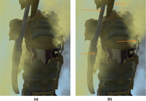
Figure 23-5 Blocky Artifacts Due to Low-Resolution Rendering
23.6.1 Edge Detection
Examine the off-screen color and alpha channels in the render target, shown in Figure 23-6. (The alpha image is inverted. Recall that we store a product of inverse particle alphas.) The blocky problem areas in the final image of Figure 23-5 are due to sharp edges in the small, off-screen buffer.
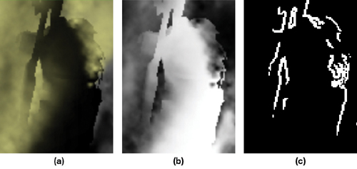
Figure 23-6 The Off-Screen Surfaces Corresponding to
The strong edges suggest that the artifacts can be fixed if we first extract the edges. Edge detection is easily achieved with a standard Sobel filter. The result is stored in another off-screen render target.
23.6.2 Composing with Stenciling
The edge-detection filter selects a small minority of pixels that are blocky. (In Figures 23-5 and 23-6, large parts of the images are cropped; on the left and right, not shown, there are large entirely black areas with no edges. But these areas of both figures still contain particles.) The pixelated areas can be fixed by rendering the particles at the full frame-buffer resolution only where edges occur.
The stencil buffer is used to efficiently mask areas of the frame buffer. When the low-resolution, off-screen particles are composed back into the main frame buffer, we simultaneously write to the stencil buffer. The stencil value cannot explicitly be set by the pixel shader. However, stencil write can be enabled for all pixels, and then the pixel shader can invoke the discard keyword to abort further output. This prevents the stencil write for that pixel, and the pixel shader effectively controls the stencil value, creating a mask. See Listing 23-4.
At this stage, the low-resolution particles have been composed into the frame buffer, and it looks like the left-hand image in Figure 23-7.
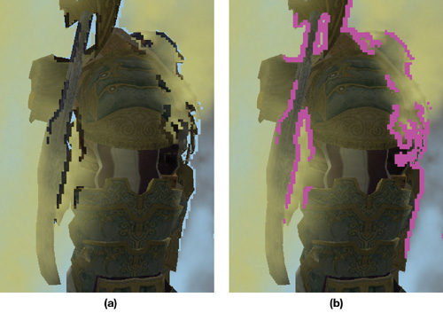
Figure 23-7 Intermediate Stages of Mixed-Resolution Rendering
The particles are then rendered a second time. The stencil states are set such that pixels are written only in the areas that were not touched by the previous compose pass—the magenta areas in Figure 23-7. The result is shown in Figure 23-8 on the right, in the next section. For comparison, the image on the left in Figure 23-8 shows the particle system rendered entirely at the full resolution.
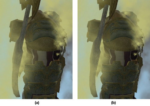
Figure 23-8 Results for Mixed-Resolution Rendering
Example 23-4. The discard Keyword Used to Avoid Stencil Writes, Creating a Mask
float4 composePS(VS_OUT2 vIn) : COLOR
{
  float4 edge = tex2D(edgesSampler, vIn.UV0.xy);
  if (edge.r == 0.0)
  {
    float4 col = tex2D(particlesRTSampler, vIn.UV1.xy);
    return rgba;
  }
  else
  {
    // Where we have an edge, abort to cause no stencil write.
    discard;
  }
}
23.7 Results
23.7.1 Image Quality
Figure 23-8 compares the full-resolution particles with a mixed-resolution result, where the off-screen surfaces are scaled by 4x4. The mixed-resolution result is very close to the high-resolution version. There are a few minor artifacts. On the character's ax, on the left-hand side of the image, there are a few small spots of the beige color. These are due to linear filtering "leaking" pixelated areas out of the edge-detected mask.
There is a detailed spike on the very rightmost edge of the high-resolution image that has been obscured by particles. Note how the edge filter missed this detail in Figure 23-7. This is a pure subsampling issue: The low-resolution surface fails to adequately represent this detail.
Finally, some high frequencies have inevitably been lost in the low-resolution image. Note the gray particles on the rightmost edge of the images. Also, there is a clump of particles on top of the character's head. Both are slightly fuzzier in the mixed-resolution image.
We thought that it would be necessary to alter the high-resolution pass to match the loss of high frequencies in the low-resolution image. A mipmap level-of-detail bias of one or two levels would reduce the high frequencies. As it is, there are no obvious discontinuities where the two resolutions meet in the final image.
23.7.2 Performance
The following tables show some results for the scene shown in all the figures. The particle system is implemented with one draw call and 560 triangles. All results were taken on a GeForce 8800 GTX at a frame-buffer resolution of 1600x1200.
To amplify the differences between the techniques, we measured these results with artificially high numbers of pixels and also for quite large pixel shaders. By contrast, for a game currently in development, we recorded 20 million particle pixels with a 16-instruction shader.
Table 23-1 shows the effect of the various techniques and the effect of the scaling factor between the main frame buffer and the off-screen buffers. High-resolution particles are always the slowest, and simple, low-resolution particles are the fastest. The more complex mixed-resolution technique is somewhat slower, due to the higher image-processing cost and increased number of operations. Note however, much higher complexity of the mixed-resolution technique does not produce a huge increase in cost over the low-resolution technique. This is because the extra image-processing passes—edge detection, stencil writes, and so on—are performed at the low resolution.
Table 23-1. The Effect of Varying Technique and Scale Factor
|
Technique |
FPS |
Particle Pixels (Millions) |
Image-Processing Pixels (Millions) |
|
High resolution |
25 |
46.9 |
0 |
|
Mixed resolution, 4x4 scale |
51 |
3.5 |
2.0 |
|
Low resolution, max z, 4x4 scale |
61 |
2.9 |
1.9 |
|
Mixed resolution, 2x2 scale |
44 |
12.0 |
2.8 |
|
Low resolution, max z, 2x2 scale |
46 |
11.7 |
2.3 |
Table 23-1 shows the cost for a pixel shader of 73 Shader Model 3.0 instructions. We artificially padded our shaders with an unrolled loop of mad instructions to simulate a complex, in-game shader. Table 23-2 shows the result of varying the number of instructions with a 2x2 scale factor.
Table 23-2. The Effect of Varying Particle Pixel Shader Cost
|
Technique |
73-Instruction FPS |
41-Instruction FPS |
9-Instruction FPS |
|
High resolution |
25 |
36 |
44 |
|
Mixed resolution |
44 |
47.6 |
50 |
|
Low resolution |
46 |
53.5 |
57 |
Table 23-3 shows the result of varying the number of particle pixels shaded and blended. This was achieved by moving progressively away from the scene, so that it shrank with perspective. As the particle system becomes arbitrarily small on screen, there comes a point at which the cost of the image-processing operations outweighs the cost of the original, high-resolution particles. The scale factor is 2x2 for Table 23-3, and the number of particle pixel shader instructions is 41.
Table 23-3. The Effect of Varying Particle System Size on Screen
|
High-Resolution Pixels (Millions) |
High-Resolution FPS |
Mixed-Resolution FPS |
|
47 |
36 |
47 |
|
32 |
43 |
52 |
|
12 |
55 |
60 |
|
3.5 |
64.4 |
63.3 |
23.8 Conclusion
The results show that our low-resolution, off-screen rendering can produce significant performance gains. It helps to make the cost of particles more scalable, so that frame rate does not plummet in the worst case for overdraw: where a particle system fills the screen. In a real game, this would translate to a more consistent frame rate experience.
Visually, the results can never be entirely free of artifacts, because there is no perfect way to downsample depth values. So there will always be some undersampling issues. However, in a game, particles such as explosions are often fast moving, so small artifacts may be acceptable. Our mixed-resolution technique often fixes many artifacts.
23.9 References
Boyd, Chas. 2007. "The Future of DirectX." Presentation at Game Developers Conference 2007. Available online at http://download.microsoft.com/download/e/5/5/e5594812-cdaa-4e25-9cc0-c02096093ceb/the%20future%20of%20directx.zip
Lorach, Tristan. 2007. "Soft Particles." In the NVIDIA DirectX 10 SDK. Available online at http://developer.download.nvidia.com/SDK/10/direct3d/Source/SoftParticles/doc/SoftParticles_hi.pdf.
- Contributors
- Foreword
- Part I: Geometry
-
- Chapter 1. Generating Complex Procedural Terrains Using the GPU
- Chapter 2. Animated Crowd Rendering
- Chapter 3. DirectX 10 Blend Shapes: Breaking the Limits
- Chapter 4. Next-Generation SpeedTree Rendering
- Chapter 5. Generic Adaptive Mesh Refinement
- Chapter 6. GPU-Generated Procedural Wind Animations for Trees
- Chapter 7. Point-Based Visualization of Metaballs on a GPU
- Part II: Light and Shadows
-
- Chapter 8. Summed-Area Variance Shadow Maps
- Chapter 9. Interactive Cinematic Relighting with Global Illumination
- Chapter 10. Parallel-Split Shadow Maps on Programmable GPUs
- Chapter 11. Efficient and Robust Shadow Volumes Using Hierarchical Occlusion Culling and Geometry Shaders
- Chapter 12. High-Quality Ambient Occlusion
- Chapter 13. Volumetric Light Scattering as a Post-Process
- Part III: Rendering
-
- Chapter 14. Advanced Techniques for Realistic Real-Time Skin Rendering
- Chapter 15. Playable Universal Capture
- Chapter 16. Vegetation Procedural Animation and Shading in Crysis
- Chapter 17. Robust Multiple Specular Reflections and Refractions
- Chapter 18. Relaxed Cone Stepping for Relief Mapping
- Chapter 19. Deferred Shading in Tabula Rasa
- Chapter 20. GPU-Based Importance Sampling
- Part IV: Image Effects
-
- Chapter 21. True Impostors
- Chapter 22. Baking Normal Maps on the GPU
- Chapter 23. High-Speed, Off-Screen Particles
- Chapter 24. The Importance of Being Linear
- Chapter 25. Rendering Vector Art on the GPU
- Chapter 26. Object Detection by Color: Using the GPU for Real-Time Video Image Processing
- Chapter 27. Motion Blur as a Post-Processing Effect
- Chapter 28. Practical Post-Process Depth of Field
- Part V: Physics Simulation
-
- Chapter 29. Real-Time Rigid Body Simulation on GPUs
- Chapter 30. Real-Time Simulation and Rendering of 3D Fluids
- Chapter 31. Fast N-Body Simulation with CUDA
- Chapter 32. Broad-Phase Collision Detection with CUDA
- Chapter 33. LCP Algorithms for Collision Detection Using CUDA
- Chapter 34. Signed Distance Fields Using Single-Pass GPU Scan Conversion of Tetrahedra
- Chapter 35. Fast Virus Signature Matching on the GPU
- Part VI: GPU Computing
-
- Chapter 36. AES Encryption and Decryption on the GPU
- Chapter 37. Efficient Random Number Generation and Application Using CUDA
- Chapter 38. Imaging Earth's Subsurface Using CUDA
- Chapter 39. Parallel Prefix Sum (Scan) with CUDA
- Chapter 40. Incremental Computation of the Gaussian
- Chapter 41. Using the Geometry Shader for Compact and Variable-Length GPU Feedback
- Preface